Daily Archives: March 24, 2014

SDRAM Controller and Modern Microprocessors – 2

We are going to take a look at the 80386DX processor today.

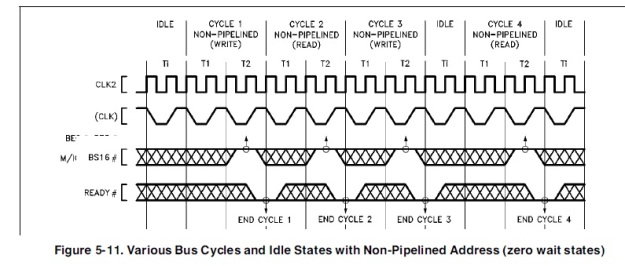
We need a RESET on the SDRAM controller. Looking at the datasheet , Address Strobe is your signal that says please start the burst cycle and what it is – (IO Read or IO Write). You know the valid address is there , the Bank Enable signals are there and you know whether you are reading or writing.

If the processor starts a read-write cycle , but you are in IDLE , you know the data is still there , you still have the address , RD/WR signals – but when you are in a refresh , so anytime when you’re in REFRESH – you make sure READY is not active.

You don’t want garbage values to be read and jank up your system. This makes the processor wait – so that the refresh is over.Every 64ms , you got to do a Refresh – that’s like 6-7 CLKs (@ CLK2 * 2) – for upto 4 of these clocks are are spent in REFRESH. So the waiting period is almost 2 CLK2 Clocks.If you can detect an IDLE peroid , you are garunteed that you will cause no more than 1 wait states and thus saving time.

Capture capture2 capture3


Capture

Reset should go into an initialization state which completes and goes into an idle state.

note – that x is the input to the driver gate. Pay special attention to this.
x = 0 when REFRESH and memory is NOT READY to Write or Read.

Things to do :

We want to wait some period of time to power supply to stable and clocks to stabilize. Wait 100microsec (no. of CLKs based on core clock rate ) , we will need a counter – this allows the memory to come online and system stabilize – (if you start running commands off bat , the memory would seem to work fine but Banks start disabling) .
So basically , wait till 100microsec before transitioning to a new state. Some time in the 100 microsec , bring CKE HIGH – clocking in a command called –  COMMAND INHIBIT or NOP.  This is done to make sure that commands are being sync’d. Then , PRECHARGE ALL.
Then wait RP time (NOP’s and DESELECT commands must be given) – now all banks are in idle state.
Issue AUTO REFRESH command and then wait RFC time to issue NOP’s.

Then – you’re ready to program mode register. The microprocessor – if it tries to do any reads-writes to memory , we need tot tell it – NOT READY!

CapturePay attention to how the initialization works. Read this document.


More insights ahead..


Direct Memory Access – Basics and how to Program it

This post is roughly based off the one done by the great pcguts guy over at osdever.net , so props to my mate there.


DMA Chip

DMA stands for direct memory access. It helps you communicate memory–>I/O and I/O –> memory.

It’s usually the 8237A-5 chips found on your motherboard. Memory–>Memory transfer fails and does not even matter because ISA DMA is glacial so you pretty much cant use it. If you use DMA to zero out the memory , it would obliterate the contents of the memory cache.

When DMA writes to memory, caches automatically load or least invalidate the data that go into the memory. When DMA reads memory, caches supply the unwritten bytes so not old but new values are transferred to the peripheral.

Our signals : DACK , DRQ and TC.

The 8237 has two electrical signals for each channel, named DRQ and -DACK. There are additional signals with the names HRQ (Hold Request), HLDA (Hold Acknowledge), -EOP (End of Process), and the bus control signals -MEMR (Memory Read), -MEMW (Memory Write), -IOR (I/O Read), and -IOW (I/O Write).

8 bit DMA channels : 0,1,2,3 || 16 bit DMA channels : 5,6,7

So when a peripheral wants to send a byte or 2 bytes of data into the memory , it issues a DRQ. The DMA controller talks to the CPU and issues DACK. The peripheral sees DACK and puts it’s data byte on the bus. DMA takes this and puts it into memory. If it was the last byte/word , DMA sets up a TC during the DACK , and when peripheral sees this TC , it kinda decides not to send any more bytes.

DMA only has a 8 bit address counter inside of it. The external ALS573 counter makes it look like DMA had 16 bit address counter per channel. There is also an extra 8-bit per address called page register (LS612) but it does not increment as it does in the ALS573. So these 24 bits of address are = 16777216 addresses.

Long story short : for each channel – 16 bits of auto-increment counter and 8 bits of fixed page register.

16 bit DMA versus 8 bit DMA ::

The address bits for a 16-bit DMA channels are wired one bit left to the address bus so every address is 2 times bigger. The lowest bit is 0. The highest bit of the page register would fit into bit 24 which is not on ISA. The bus-control logic is such that every single DMA transfer – a 16 bit cycle is generated – ISA device puts 16 bits on the bus at the time.

In comparison , the 8-bit DMA increments by 1 , cycles inside 65536 bytes addresses 16 MB and moves 8 bits at a time.

16-bit DMA increments by 2 , goes only over even addresses , cycles inside 131072 bytes , addresses 16 MB , moves 16 bits at a time  and is faster than 8-bit cuz it takes less ticks to move one cycle using 16-bit ISA I/O (faster than 8-bit DMA)

—————————————

Example :

SOUND BLASTER

This is the Sound Blaster audio card.  It can play samples in the background. The CPU sets up the sound card and the DMA. When the DMA is allowed to ‘go’ , it takes data from RAM to the card. This means the CPU can do other things and not bother about the sound samples.


Understanding Pages : Consider the first 16MB of your memory. It’s divided into 256 pages of 64K or 128 pages of 128 K. Every page starts at multiple of 65536 or 131072 , being numbered from 0-255 or 0-127.


Programming this bad boy :

What you need  to know : Number of DMA channels to use , what page to use and what offset in the page , the length of the data to transfer , how to let the peripheral realize it needs to ask for a DMA.

What you cannot do (or think you can’t) : Cant transfer more than 64K or 128K in one shot. Cant cross page boundary -cuz if you do , the lower 16-17 bits will wrap  and you jump from 65536 to 131072 bytes lower than what you would expect.

The length that is sent to DMA is actually DMA(length+1). That means that if you transfer a DMA of length 0 , it actually transfers 1 word/byte. If you send 0xFFFF , it transfers 64K or 128K.

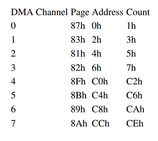
Channels


DMA Channels

DMA Channels

Please note : DMA does not exist. It’s used to cascade two 8237A’s. It issues HRQ to second chip’s DRQ 4. The second chip thinks DMA 4 needs priority so issues DRQ4 to first chips HLDA. First chip makes its own DMA 0-3 , then sends to the second chip – “OK. DMA4 complete.” and the second chip knows it’s free on the bus. It’s kinda tricky.

– Shreyas Gune